Folded images in mirages
Magnification and refraction
Because refraction generally raises the apparent position of objects above
their geometric positions, it
compresses
more than a hemisphere of the
real sky into the hemisphere above the astronomical horizon. So the
effect of standard refraction is to compress objects seen near the
horizon.
However, mirages involve rapid changes in refraction with apparent
altitude. Some zones of the sky are compressed more than normal; others
are compressed less, or even expanded.
This effect is particularly important in the
inferior mirage,
for it's what makes
inferior-mirage
flashes
thick enough to see with the naked eye.
Unfortunately, the expanded zone is usually only a couple of minutes of
arc wide — near the limit of resolution of the unaided eye. But
even one minute of arc is about four times the normal width of the
green rim,
so it represents an important magnification of this feature, which is
the source of the inferior-mirage flash. When
seen through a magnifying mirage, the green rim
can become big enough to see easily.
The transition zone
The transition between the erect and inverted images in inferior mirages
is continuous: there is no sharp demarcation between the two images. At
the line where the image seems to “fold over” and invert,
there is great vertical magnification of the image; random landscape
features appear stretched vertically, sometimes looking like the raised
pile on a carpet.
This continuous transition was first noticed by William Hyde Wollaston
on Aug. 22, 1800.
In a paper
read to the Royal Society two years later, he wrote:
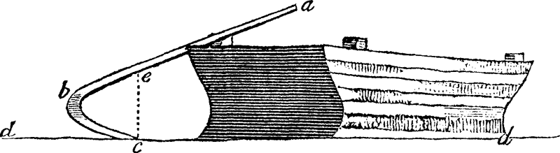
I was sitting in a boat near Chelsea, in such a position that my eye was
elevated about half a yard from the surface of the water, and had a view
over its surface, that probably somewhat exceeded a mile in length, when I
remarked that the oars of several barges at a distance, that were then
coming up with the tide, appeared bent in various degrees, according to
their distance from me. The most distant appeared nearly in the form here
represented; dd being my visible horizon by apparent
curvature of the water; ab the oar itself in its inclined
position; and bc an inverted image of the portion be.
By a little attention to other boats, and to buildings on shore, I could
discern that the appearance of all distant objects seen near the surface
of the water was affected in a similar manner, but that scarcely any of
them afforded images so perfectly distinct as the oblique line of an oar
dipped in the water.
A person present at the time (as well as some others to whom I have
since related the circumstance) was inclined to attribute the appearance
to reflection from the surface of the water; but, by a moderate share
of attention, a very evident difference may be discovered between
the inversion occasioned by reflection, and that which is caused by
atmospherical refraction. In cases of reflection, the angles between the
object and image are sharp, the line of contact between them straight and
well defined, but the lower part of the image indefinite and confused,
by means of any slight undulation of the water. But, when the images
are caused by refraction, the confines of the object and its inverted
image are rounded and indistinct, and the lower edge of the image is
terminated by a straight line at the surface of the water.
The bend at b in the image of the oar is where the
vertical magnification becomes infinite, so the sloping oar appears
to be vertical there. The doubly-imaged portion cbe of
the oar in Wollaston's diagram corresponds exactly to the right-hand
“foot” of the
Omega shape
produced when the Sun begins to sink below the horizon in
such conditions (see the
photographs
of this taken by George Kaplan, as well as my
simulation
of such a sunset).
It also corresponds to the left-hand end of the green flash produced
when the green upper rim of the Sun is seen through the transition zone.
In both cases, the Sun's limb is sloping from upper right to lower left,
exactly like the actual oar in Wollaston's diagram.
Notice that the points marked c and e , which
are connected by a vertical dashed line in the diagram, are two images of
the same point on the oar. Refraction acts only in the
vertical direction; so the erect and inverted images are aligned
vertically. Also, note that the smooth transition from erect to inverted
image is visible on the sloping sides of the barge itself.
How could Wollaston see this?
I began by pointing out that the zone of large magnification is usually too
narrow to be seen by the naked eye. How, then, did Wollaston manage to
notice the bend in the oar?
The answer lies in the closeness of his eye to the water. The closer the
eye is to the warm surface, the larger is the angular extent of the
mirage. Wollaston says his eye was “half a yard” [or half a
meter, in modern units] above the surface. That's why inferior-mirage
flashes are usually seen from beaches, or from the decks of ships.
Indeed, by fitting a mirror to the objective of a pocket telescope,
Wollaston found that the greatest separation of the points corresponding
to c and e in his diagram was seen
“within an inch or two” of the surface, when the water was
calm.
Why is height so important?
But why does the inferior mirage depend so strongly on height of the eye?
The answer lies in the shape of the temperature profile above a warm
surface.
Above a height of several meters, the temperature profile is nearly a
linear function of height.
The lapse rate
is near the adiabatic lapse rate (about 10° C per
kilometer) expected for free convection.
But, as we approach the surface, the
temperature increases more and more rapidly.
The increasing steepness of the temperature profile is due to the
interference of the Earth's surface with the convective heat transfer:
at a height h, the largest eddies (which transfer heat most
effectively) cannot be larger than about h. So, as the vertical heat
transfer by convection becomes less and less efficient as we approach the
surface, the temperature gradient has to become steeper and steeper to
maintain a (steady-state) constant heat flux.
Now, a constant lapse rate corresponds to (nearly) a constant density
gradient. Optically, it's like a
prism:
images are displaced, but not
(very) distorted. To produce distortion, we need a lapse rate that changes
rapidly with height.
That's exactly what the convection above a hot surface provides.
From an optical point of view, the erect image above the fold line is a
virtual image: the atmosphere acts like a
prism,
not like a lens. (The image is displaced, but only slightly distorted.)
Below the fold line, the rapid change in temperature gradient with height
makes the atmosphere act like a positive, cylindrical lens, which forms
a real, inverted image: the inferior mirage. This lens is located near
the apparent horizon.
The power of this lens is proportional to the curvature of
the density (or temperature) profile. Because of the rapid change in
slope of the temperature profile, the power of the
atmospheric lens varies rapidly with height. It's strong near the
surface, and weak a few meters higher up. Near the surface, the focal
length of the atmospheric lens is much shorter than the distance from the
eye to the horizon, so the real, inverted image of a distant object is
localized near the lens (i.e., near the apparent horizon). Only objects
beyond the lens — beyond the horizon — can be imaged by the
lens. So only objects beyond the horizon appear miraged.
But exactly at the fold line, the focal length of the atmospheric lens
is exactly equal to the distance from the lens to the eye: a point on
the Sun (if it's the miraged object) fills the pupil of the lens, and
appears big to the eye. If that point is in the
green rim,
the eye sees a
green flash.
So the fold line appears at the altitude
where the focal length of the atmospheric lens
approximately equals the distance from the eye to the apparent horizon.
The lower the eye, the shorter is the distance to the horizon, and the
closer and more powerful is the lens at the fold line. This makes the
mirage look bigger.
For a more technical treatment of inferior mirages, in which Wollaston's
bent oar is used as an example, see my
2015 paper.
A note on scale
It may help to appreciate the scale of the barge and oar in the figure
above. Cargo was transported up and down the
Thames estuary on these “dumb” (i.e., un-powered) barges,
or lighters, until World War II. The long oars or “sweeps”
were typically 20 to 30 feet long — say, 6 to 9 meters. The barges
themselves were of shallow draft — about 1.5 meters — with
displacements from 20 or 30 tons up to over 100 tons, and lengths on the
order of 20 meters. Their beam was limited to 4 or 5 meters, because of
the need to pass through locks and under bridges. The freeboard might
have been 1 or 2 meters when empty, as the one in Wollaston's drawing
appears to have been. The barges were steered (and propelled) with a
single oar at the stem of the vessel, just as shown in his drawing.
Wollaston
Wollaston's paper contains the first occurrence of the French word
mirage in the English language, so far as I know.
Unfortunately, his main interest was in measuring the
dip of the horizon
for navigational purposes, so many later workers in atmospheric optics
overlooked this paper. (The title, Observations on the Quantity of
horizontal Refraction; with a Method of measuring the Dip at
Sea , is not one to attract the attention of
someone interested in mirages.)
Wollaston was an interesting fellow. He discovered the dark lines in
the solar spectrum (later studied in detail by Fraunhofer, and so named
after him rather than Wollaston) in the same year he delivered his
paper on refraction (1802). In July of the same year, he discovered
the metal palladium, and offered it for sale anonymously, through
a dealer. Also in 1802, he measured the refractive index of Iceland
spar in different directions and showed that the extraordinary ray
was refracted exactly as predicted by Huygens's wave construction,
which helped establish the wave theory of light. In the same year, he
introduced the total-internal-reflection method of measuring refractive
indices — ironically, many people still try to explain inferior
mirages by total internal reflection, despite Wollaston's clear
demonstration
that refraction is involved.
In 1804, he announced the discovery of rhodium.
A year later, he found a way to make platinum malleable, and began to sell
laboratory apparatus made of platinum.
He invented the camera lucida and improved the camera obscura; both
played a part in the invention of photography. In 1812 he discovered
“cystic oxide”, which turned out to be cysteine, the first
of the amino acids to be discovered.
Today he is chiefly remembered for the Wollaston prism, introduced as part
of an optical micrometer he invented.
Copyright © 2005, 2006, 2008, 2012, 2014, 2020, 2021 Andrew T. Young
Back to the . . .
GF simulations
or the
main mirage page
or the
GF home page
or the
website overview page