Introduction to the Mirage Simulations
The Target
A mirage is an image of something ; so before making
simulations of mirages, you have to decide on what object is to be miraged.
(This isn't a problem with
sunset mirages,
where the object is necessarily the Sun.)
To simplify the work, the object should have a simple shape. I've chosen
a triangle with a 90° vertex at the top, so that the sides slope at
45°. In addition, I've painted some stripes on the triangle parallel to
its left edge; these are sometimes useful in distinguishing inverted and
erect portions of the miraged images.
Although one occasionally sees conical hills with a triangular profile,
they don't have stripes; so I'll call my object a “target”, to
emphasize its artificiality.
 To understand mirages, it's very useful to know what the scene looks like
without a mirage. So here's a simulation of the target's
appearance as seen from a height of 1.5 m through just 2 km of the
Standard Atmosphere.
This is essentially an undistorted view of the target.
To understand mirages, it's very useful to know what the scene looks like
without a mirage. So here's a simulation of the target's
appearance as seen from a height of 1.5 m through just 2 km of the
Standard Atmosphere.
This is essentially an undistorted view of the target.
Parts of the diagram
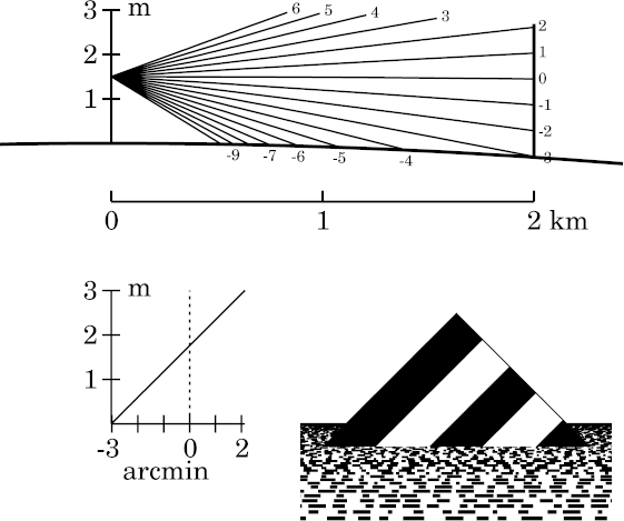
Each drawing in these simulations contains three parts: a ray diagram, a
transfer curve, and a simulated image of the target.
The ray diagram
At the top of the simulation is the ray diagram, showing a fan of
rays that enter the observer's eye, at the left edge.
(Here the rays are practically straight.)
The right end of each ray is marked with its apparent
altitude
at the observer, in
minutes
of arc.
The vertical scale, at the left side, is height in the atmosphere. You
can read off the observer's height by noticing where on this scale the
rays all converge. The horizontal scale is horizontal distance; the plot
is correct in rectangular coordinates, so the heavy line that represents
the Earth's surface is concave downward.
Obviously, the ray
diagram is grossly exaggerated in the vertical direction, to make its
details visible. (Note that the vertical scale is in meters, and the
horizontal one, in km.) The target here has twice the height of the
observer's eye; this puts the middle of the target at eye level.
The transfer curve
Below the ray diagram, and to the left of the simulated image, is a
simple transfer curve that shows height at the target (the
vertical scale) as a function of altitude at the observer. As expected,
this curve is a straight line of (effectively) unit slope: the image is
not distorted.
The vertical dotted line in this plot marks the
astronomical horizon.
Notice that the vertical scales on the transfer curve and the
ray diagram
are identical.
However, the target is at the right side of the ray diagram; as the
vertical scale of the transfer curve has its zero level at the surface
of the Earth, which is lower in the ray diagram at the target than at
the observer, this is offset from the vertical coordinate of the ray diagram.
The simulated image
The image of the target itself has been scaled to fit in the lower right
corner. The Earth's surface is represented as covered with irregular
but equally-spaced rulings parallel to the horizon — much as the
surface of the sea might appear, with waves parallel to the shore.
In the example shown, it's clear that the target is much closer than the
sea horizon, which is seen in the distance behind it. The target resembles
a triangular island rising from the sea. The overall effect is not
very realistic, but is suggestive enough to give an impression of what the
atmosphere might do (in this case, nothing) to the appearance of a simple
object.
The Simulations
Simulations of some common mirage types are available at the links below:
-
inferior mirages;
-
and, for comparison, terrestrial refraction in the
Standard Atmosphere
under similar circumstances;
-
mock mirages, both
- ordinary, and
- ducted;
and
-
superior mirages.
In addition, there are
simulations
of looming, towering, sinking and stooping, although these related
refraction phenomena
are not themselves mirages.
Notice that the size of the target changes from one set of
simulations to the next. For the inferior-mirage simulations, the
observer is close to the surface; the apparent horizon is not far away;
and a small target, only 3 m high, is used, to make the mirage
effects plain. (The same small target is used in the Standard-Atmosphere
and looming simulations.) But for the mirages that involve
ducts,
like the mock mirage and superior-mirage simulations, a much larger
target height (200 m) is appropriate.
Making the simulations
To make a mirage simulation, it's necessary to use a model of the lower
atmosphere to trace rays between the eye of the observer and the target.
The procedure is much like making
sunset simulations:
start with a
temperature profile,
from which you calculate a
density
profile, using
hydrostatic equilibrium
to determine the pressure at each level; from the density,
calculate
a refractivity profile; use that to trace
rays
backward from the observer to the target, using the relationship between
ray bending
and the refractivity
gradient.
The relation between the angular
altitude
of each ray at the eye to its height at the target is the
transfer curve
for the mirage. Given the transfer curve, it's easy to draw the apparent
distorted shape of the target seen through the refracting atmosphere.
As with the sunset simulations, I have a program that generates the output
drawing as a PostScript figure. I then
convert
that to a PNG file for the appropriate Web page.
Finding your way around in the simulations
Because there are many pages here dealing with mirage
simulations, and it's often difficult to see how they all fit together,
you may find the
Mirage section
of the
Table of Contents
helpful.
Copyright © 2008 – 2012 Andrew T. Young
Back to the . . .
main mirage page
or the
GF home page
or the
website overview page