 A step in this direction is possible with the aid of an image that
contains all 256 possible gray levels.
A step in this direction is possible with the aid of an image that
contains all 256 possible gray levels.
Remember dot-matrix printers? Well, modern inkjet and laser printers use different means to accomplish the same result: little black dots on paper. The dots have gotten smaller, but the principle is the same: build up characters (or images) with suitably-placed back dots.
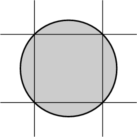
The trouble with these dots is, they're round. But pixels — those little pieces that digital images are supposedly composed of — are square. And trying to make up a picture of square pixels from round dots is like (ahem) trying to put a square peg into a round hole. They just don't fit.
The standard way of forcing a round dot into the space that should be occupied by a square pixel is to make the dot over-sized, so that when all the pixels are painted with round dots, there aren't any gaps left between them. That way, what's meant to be solid black comes out solid black — which is usually what we want.
Unfortunately, when we're trying to represent shades of gray instead of solid black, there are problems. That's why digital halftoning doesn't come out the way it's supposed to, in the Real World.
In reality, the dots aren't laid down on a mathematically perfect grid; there's a little jitter or error in their positions. So, to make sure that black is still really black, the dots are usually made a bit bigger. (Sometimes they're a lot bigger.)
Now, the area of a circle is πD2/4, while the area of a square of side S is just S2. If D = √2 S, D2 = 2S2. So the area of the circumscribed circular dot is 2π/4 = π/2 = 1.57… times the area of the square pixel.
Right away, that means that even the lighter grays (where the dots don't overlap) will come out about 57% darker than they should. [Actually, the dots are usually larger than the minimum size needed to avoid gaps, so the extra darkening is considerably more than this.]
The discrepancy is considerably worse when we have a dark area in which a single white pixel is surrounded by black ones. Now the white pixel is deprived of that area by which the dot exceeds the area of the desired square; so it's (at best) only 43% as big as it should be. If the dots are oversized, the situation rapidly grows worse. The dots will overlap an isolated white pixel completely if their radius is S, which makes their diameter 2S — only √2 times the minimum diameter to avoid gaps. Then what should be a half-white checkerboard of alternating black and white pixels will be completely black!
Before you reject this possibility as absurd, I should mention that this is close to what really comes out of my HP LaserJet III printer. As a result, uniform gray areas digitally halftoned with the standard Floyd-Steinberg method come out nearly black, once the fraction of black pixels exceeds 50%.
By a curious coincidence, this is close to the behavior of data that are gamma-corrected for a standard CRT monitor, such as a normal PGM file. That's why just running a standard PGM file through the pgmtopbm command often produces a reasonable-looking result.
However, the dot-overlap effects at higher densities, in the darker parts of the image, no longer fit the power-law transfer curve that relates CRT brightness to gamma-corrected PGM data. That means that you can't really correct an image for the printer's behavior by applying a simple transfer-curve correction. We really need to model the printer accurately, and take this model into account in the halftoning process.
Easier said than done! Few users will have a reflectance photometer handy. What we need is a way to characterize printers with enough accuracy to achieve useful results; only the most exacting of professional printers will need to measure their output photometrically.
A step in this direction is possible with the aid of an image that
contains all 256 possible gray levels.
Here's an image of gray squares that includes all the values from 1 to 255 (which is a little more convenient than the 256 levels from 0 to 255, because we can put 15 squares in a row here; then the last square in the first row has gray level 15, the last in the second row has gray level 30, and so on).
You can save a copy of this PNG image by using the “Save Image As…” item on the menu that Mozilla pops up if you right-click on the picture with the mouse. Once you have a local copy to play with, you can convert it to PGM format with the pngtopnm command, and then use pgmtopbm to experiment with dithering algorithms, and see how your own local printer renders the results.
A larger version, suitable for high-resolution printers, is available here. Other calibration images are available, too.
However, both inkjet printers and the newer high-resolution laser printers do not print accurately reproducible, circular dots. Inkjets have dot-placement jitter, and high-resolution laser printers tend to produce gray smudges instead of sharp dots. The overlapping-dot model then does not model their behavior accurately, and a more complicated model is required.
Unfortunately, pgmtopbm doesn't have such corrections available.
It might seem surprising that paper is translucent enough for this to be a significant effect. But, consider: it's easy to see what's printed on a page covered by a single sheet of laser-printer paper, which shows that several per cent of the light can get through the thickness of the paper twice. If 4% (1/25) of the light gets through the paper twice, about 20% (1/5, the square root of 1/25) will pass through once. That makes the optical depth of the sheet only about 1.5 — certainly not infinity.
But the thickness of a sheet of paper is similar to the dot spacing (1/300 inch), if you notice that a ream (500 sheets) of paper is not quite 2 inches thick. That means that the diffusion length of light in paper is comparable to the dot spacing, even at 300 dpi.
This effect of neighboring dots is variously known as “optical dot gain” or the “Yule-Nielsen effect”; Google will tell you more. The effect of light scattering within the paper means that the simple dot-overlap model isn't adequate to model real printers — especially, the newer, higher-resolution ones. Proper allowance for this seems to require some reflectance measurements, and really complicated printer modelling.
On the other hand, some newer printers contain their own halftoning algorithms that do a better job than the old clustered-dot halftoning (which imitates the even older analog screening methods of traditional photographic halftoning) that was used in the first-generation laser printers. Thus, it may be worth while sending a grayscale (rather than a binary) image to a modern laser printer, as a test.
anytopnm image.png | pnmtops −dpi 300 −equalpixels > image.ps
If your printer isn't a 300 dpi printer, use its number of dots per inch in place of 300 here.
If a test printing of the grayscale image shows satisfactory rendering by the printer itself, you can try this same method on the bilevel version of the image you really want to print.
However, beware: printing a grayscale well is not proof that the printer can print a detailed image. For example, our HP 2420dn prints the grayscale image very nicely, using its internal halftoning algorithm. But when I try to print the image I'm really interested in, I get very offensive moiré fringes in the shaded regions. Evidently, the printer is using a conventional screening technique that beats against the regularly-spaced shading lines in the image. This printer would do a good job of halftoning a typical photograph, but not the shading details of a 19th-Century wood engraving.
Copyright © 2006 – 2008, 2012 Andrew T. Young
or the
GF home page
or the website overview page