Mock-Mirage Simulations
Introduction
Here are some mock-mirage simulations of my
usual target.
Because these phenomena require the observer to be above the
thermal inversion
that produces them, a much taller target is needed here to display the
range of phenomena than was required for the
inferior-mirage simulations.
The thermal inversions here have heights on the order of 50 meters, so
a target height of 200 meters works well.
That makes it look like a small island in the sea, or a fair-sized
hill on land.
The simulations fall into two groups:
ordinary mock mirages
without ducting; and
ducted mock mirages.
Comparisons
 Before you look at the detailed simulations for the two different
sub-types, a little comparison of ordinary and ducted mock mirages may be
useful. I've placed the observer 5 meters above the top of the inversion
in each case, although the inversion that produces a duct is a little
higher than the one that doesn't.
Bear in mind that the simple mock mirages are produced by a weaker thermal
inversion than the ducted ones. That means that the width of the miraged
(inverted) zone is smaller for the plain ones. Try to ignore such
quantitative differences, and concentrate on the qualitative differences
between the two types.
Let's start by comparing the two mock mirages for targets 40 km away,
which puts the target well beyond the horizon, and allows the
characteristic features of each type to be visible.
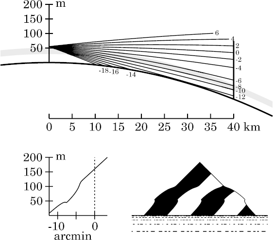
At the right is a simulation of an ordinary mock mirage, without ducting.
Notice the structure around an altitude of −8′,
where a ray is tangent to the bottom of the thermal inversion (shown
shaded, as usual). The mock mirage is the little glitch in the image at
that altitude. It sticks out like the overhanging lip of a cliff.
The deformation of the erect part of the
image between altitudes of about −7.5′ and
−4′ is due to the top of the inversion; it's not
part of the mock mirage. However, it is a significant
difference between an
ordinary mock mirage
display, and a
ducted one.
(This deformed zone is discussed in more detail
below).
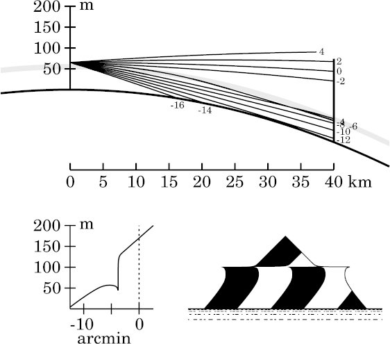
 Now let's look at a ducted mock mirage of the same target, at the same
distance. That's shown on the left.
While the top third, or a little more, of the target is undistorted in
both situations (because it's seen through air with the standard lapse
rate of 6.5K/km), the lower parts are different. In the ducted
mock mirage, the overhanging lip is a lot more obvious, as we'd expect
from the stronger inversion required to produce ducting.
But what's really striking about the ducted display is that the part of
the target between the mock mirage (which is roughly the middle third
of the image here) and the undistorted top third is completely missing.
The inverted image zone terminates at a horizontal line here, and the
undistorted top sits directly on that line.
That sharp horizontal boundary is the top edge of the duct. Rays that
enter the duct, like the one at an altitude of −4′, are bent
down so sharply that a whole section of the target, just above the
inversion, is invisible from the observer's position. The top of the
inversion, which is also the top of the duct, looks like a solid horizontal
surface that blocks the observer's view of this part of the target.
(Look at the big gap between the rays at −4′ and
−2′ in the ray diagram.)
Strictly speaking, the zone of the target that seems to be missing here is
actually present — but so extremely compressed that it can't be
discerned.
This is a particular example of an effect that's seen whenever the
line of sight can be horizontal near the top of a duct: the duct top
generally appears as a horizontal line in the refracted imagery.
Height effects
 Because the mock mirage is produced by the change in lapse rate at the
base of an inversion, it's visible to most observers above
that base. But the shape of the
stooped
zone above the mock mirage changes when the
observer passes through the top of the inversion.
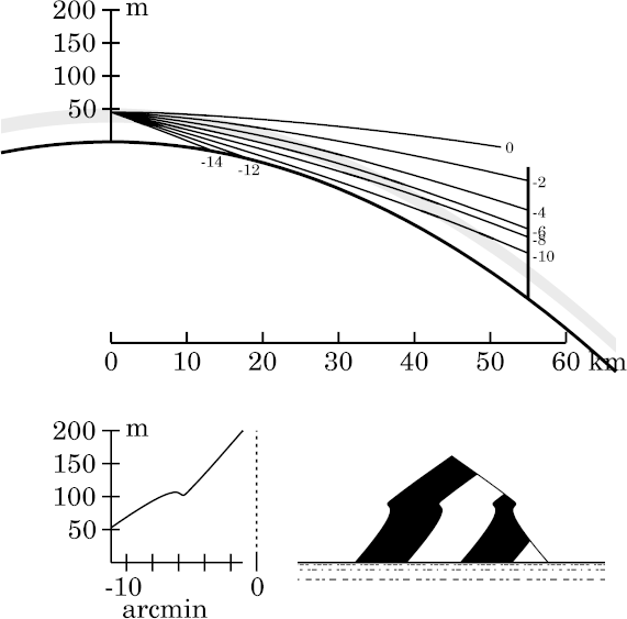
At the right is an ordinary mock-mirage simulation for an observer at
45 m height, which is 5 m below the top of the
inversion.
(The rest
of my ordinary mock-mirage simulations are for an observer 5 m
above the top of the inversion.)
I've moved the target out to 55 km to get a better example of the effect.
Notice that the part of the target above the mock mirage — i.e., the
top third — appears slightly stooped, but not seriously deformed.
(The stooping is shown by the flattening of its vertex: in the actual
target, the vertex angle is a right angle; but here, it appears obtuse.)
Despite the stooping, the sides are still straight.
The
transfer curve
also shows this effect: the top end of it is steeper
than the relatively normal bottom part. A steep transfer curve
corresponds to a stooped image.
But the steep part of the curve is straight; so straight lines in the
stooped zone appear straight, although slightly compressed vertically.
Here, the whole upper part of the target is seen through the change in
lapse rate at the top of the inversion. But that change
acts like a negative (minifying) lens, which reduces the height of the
image. This is a simple way of explaining the stooping.
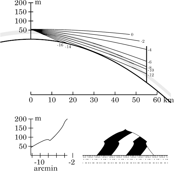
 Now compare that situation with the view from just 10 m higher up, at
55 m; that's 5 m above the top of the inversion,
instead of 5 m below it.
This higher observer sees the image simulated at the left. Here, the
observer looks down into the top of the inversion, and then out of it
again, when viewing the upper third of the target — e.g., the rays
at −4′ and −6′ altitude. (This top third of the
target occupies about the top half of its
image , above −7.5′.)
Of course, the negative-lens effect is still at work, so this region is
stooped.
The stooping is considerably greater than before, which is reasonable, as
we now look through the change of gradient at the top of the inversion
twice .
But the stooping is not uniform: the upper part of the image is
flattened much more than the part just above the mock mirage.
The reason for the greater stooping higher up is that the line of sight
is tangent to the top of the inversion near the top of the target;
see the ray whose altitude is −4′, for example.
So rays from near the top of the target have grazing
incidence at the top of the inversion, while those lower down meet that
surface at a bigger angle. Consequently, the path
length in the negative-lens region at the top of the inversion is longer
for rays near the top of the target. This makes the minifying effect
greater near the top of the target, and smaller near the mock mirage.
So the straight sides of the upper part of the target become curved lines
in its image.
By the way, notice that the mock mirage itself
(the inverted zone in the image) looks very similar in these
two cases: changing the height of the eye hasn't made much difference in its
appearance. Only the part of the image above the inverted
zone depends on whether the observer is above or below the upper
surface of the inversion layer.
Copyright © 2008 – 2009, 2012, 2022, 2024 Andrew T. Young
Back to the . . .
introduction to mirage simulations
or the
main mirage page
or the
GF home page
or the
website overview page
 Before you look at the detailed simulations for the two different
sub-types, a little comparison of ordinary and ducted mock mirages may be
useful. I've placed the observer 5 meters above the top of the inversion
in each case, although the inversion that produces a duct is a little
higher than the one that doesn't.
 Now let's look at a ducted mock mirage of the same target, at the same
distance. That's shown on the left.
 Because the mock mirage is produced by the change in lapse rate at the
base of an inversion, it's visible to most observers above
that base. But the shape of the
stooped
zone above the mock mirage changes when the
observer passes through the top of the inversion.
 Now compare that situation with the view from just 10 m higher up, at
55 m; that's 5 m above the top of the inversion,
instead of 5 m below it.