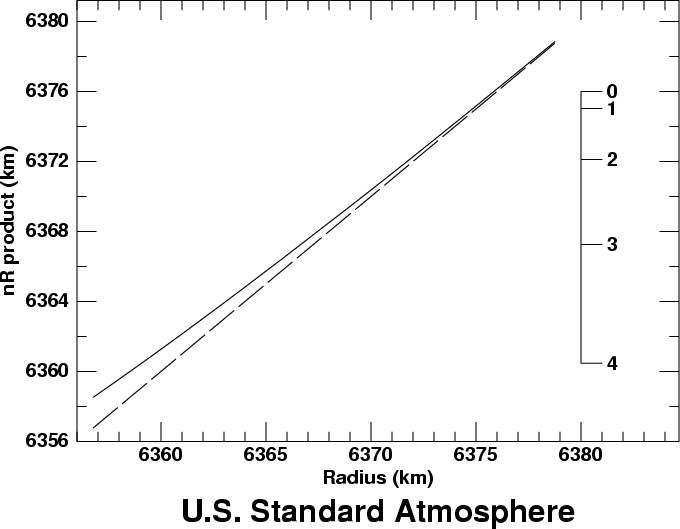
 The solid line in the graph shows nR as a function of R,
for the bottom 22 km of the Standard Atmosphere.
The dashed line is the function nR = R; the solid line
approaches it asymptotically at large heights, because
n → 1 at large heights.
The dip diagram is a graph based on the refractive invariant, the quantity I = (n R sin z), which has the same value, I, at all points along a ray of light. Here, n is the refractive index of air at a distance R from the center of the Earth, and z is the zenith distance of the ray at that point.
Symmetry makes a ray horizontal at its lowest point, or perigee. There, z = 90°, so (sin z) is unity, and nR = I. Then the ratio of (nR) at any other height to the value of (nR) at the perigee gives (sin z) at that other height. This means we can determine that ray's slope at any height from a plot of (nR) vs. height — which is the dip diagram.
Because the zenith distance z is the complement of the altitude, h, sin z = cos h. So we can also say that nR/I = cos h. In particular, the ray at an observer's sea horizon is horizontal at the sea surface; so the cosine of the dip of the horizon seen from any height is just (nR at sea level) divided by (nR at the observer).
The dip diagram is just a plot of (nR) as a function of height or R. Here's an example, based on the Standard Atmosphere:
 The solid line in the graph shows nR as a function of R,
for the bottom 22 km of the Standard Atmosphere.
The dashed line is the function nR = R; the solid line
approaches it asymptotically at large heights, because
n → 1 at large heights.
The scale at the right side of the diagram is graduated in degrees of dip for an observer placed 19 km above the Earth's surface. That is, the graduation marked “0” is at the value of nR for a height of 19 km; the graduation marked “1” is at the value of nR for a height of 19 km, multiplied by the cosine of 1°; the “2” marks the observer's value of nR multiplied by the cosine of 2°; and so on. The dip of the horizon for this highly elevated observer is a little more than 4°, because the surface of the Earth (at the left end of the model curve) is a little below the 4° mark on the scale.
This example showed a big interval of height on the diagram, to illustrate the fact that nR → R at the top of the atmosphere, where the refractive index, n, approaches unity. Most of the time, it's more useful to show a much smaller piece of the diagram, just above the surface of the Earth. And it's more convenient to use height for the horizontal scale, instead of distance from the center of the Earth.

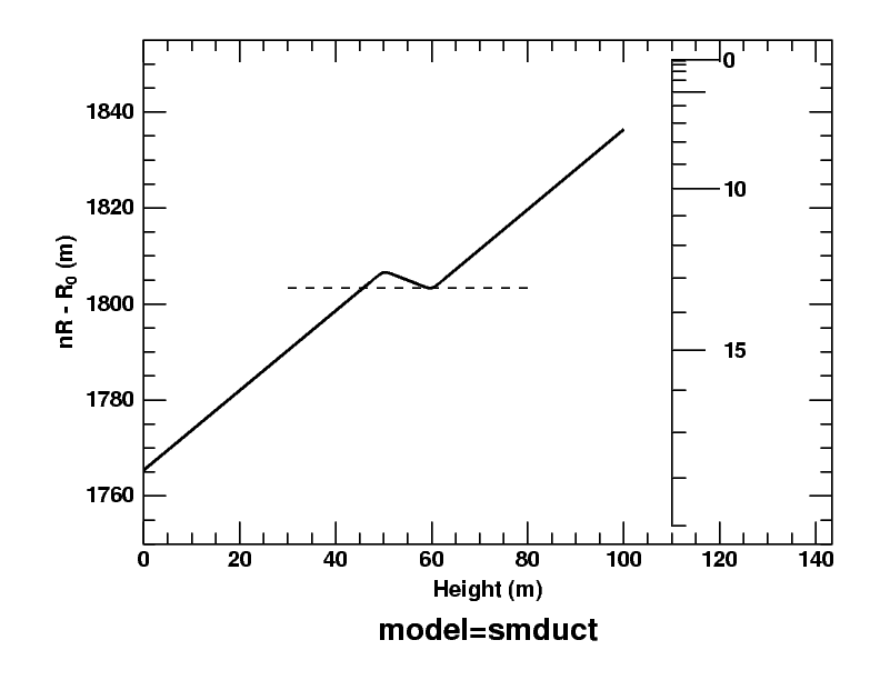
Here's the dip diagram for a duct model I've used repeatedly on these pages; the 2° thermal inversion that produces the duct extends from 50 to 60 meters. As I proposed above, height is the horizontal axis; the dip scale on the right is now graduated in minutes of arc rather than degrees, because only the bottom 100 m of the atmosphere is shown.
Because the temperature gradient is so steep in the inversion, the nR product actually decreases with height there. So there is a minimum in the diagram at the top of the inversion (60 m).
I've drawn a dashed horizontal line tangent to this minimum. You can see that it intersects the curve for the model atmosphere a little below the inversion, at about 45 m. At that height, nR has the same value as at the top of the inversion. Any ray with a slightly larger value of nR within the region between the maximum and the dashed line is trapped, oscillating forever between two limiting heights. (You can see a picture of such rays on the mirage page.)
If you slide the dip scale at the right over to the curve, so that the zero of the dip scale is at the maximum, you'll see that the dip of the duct edges (where the dashed line meets the solid curve) — as seen from the base of the inversion — is 3 or 4 minutes of arc. That's the half-width of Wegener's “blank strip”, which is centered on the astronomical horizon.
Finally, because nR has the same value at the top and bottom of the duct, any ray passing obliquely across the duct has the same inclination to the horizon at both those heights. (This follows from the refractive invariant.)
Dip diagrams are discussed in more detail in
A. T. Young & G. W. Kattawar
Sunset Science. II. A Useful Diagram
Applied Optics 37, 3785-3792 (1998).
Copyright © 2003 – 2010, 2012, 2013, 2025 Andrew T. Young
or the
astronomical refraction page
or the
GF home page
or the Overview page