 Let's take a closer look at the atmospheric model used in this simulation.
The same format used in the mirage simulations is used here. The target is the same triangle, 3 meters high, that is used in the Standard-Atmosphere and inferior-mirage simulations; and the same eye height (1.5 meters) used for them is retained here. To make the effects sufficiently visible, I've chosen to put the target 10 km away from the observer.
As in the mirage simulations, I'll provide alignment links to allow blinking various examples against a reference case that shows the target as seen through the Standard Atmosphere.
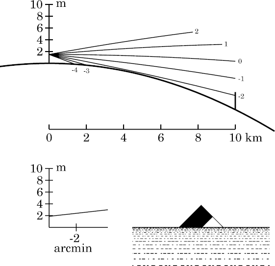
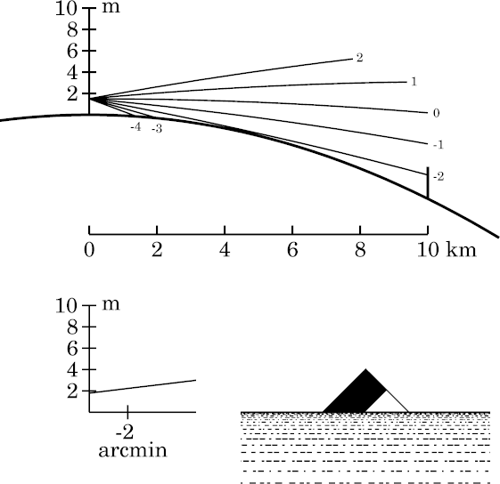 That example of “normal” refraction is shown here at the left.
The 10-km viewing distance is a little larger than the most remote example
shown on the
standard-refraction page,
which was 9.5 km. So the target has sunk a little farther below the
horizon here. You can see that just 2 of the 5 stripes on the target are
visible above the apparent horizon, which is about 4.5 km away.
That example of “normal” refraction is shown here at the left.
The 10-km viewing distance is a little larger than the most remote example
shown on the
standard-refraction page,
which was 9.5 km. So the target has sunk a little farther below the
horizon here. You can see that just 2 of the 5 stripes on the target are
visible above the apparent horizon, which is about 4.5 km away.
Note that the rays are curved, because of the
temperature gradient
in the lower atmosphere; see the
bending page
for details.
As Talman (1932) says,
When abnormal refraction increases the apparent elevation of distant objects — often lifting above the horizon things normally below it — the process is described as ‘looming.’. Because we associate a certain apparent altitude with a certain distance, this phenomenon generally makes the objects seem nearer than they really are.
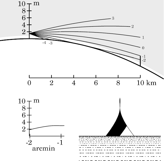
 To simulate this effect, it's convenient to choose a temperature gradient
that makes the ray curvature about half that of the Earth, instead of the
usual 1/6 or 1/7 (the value Lambert inferred, by the way). If you look at
the
bending page,
you'll see that a temperature inversion of about 0.11°/m will make the
ray curvature match that of the Earth; so I've chosen 0.05°/m, or 5
degrees in 100 m, as the inversion to use.
To simulate this effect, it's convenient to choose a temperature gradient
that makes the ray curvature about half that of the Earth, instead of the
usual 1/6 or 1/7 (the value Lambert inferred, by the way). If you look at
the
bending page,
you'll see that a temperature inversion of about 0.11°/m will make the
ray curvature match that of the Earth; so I've chosen 0.05°/m, or 5
degrees in 100 m, as the inversion to use.
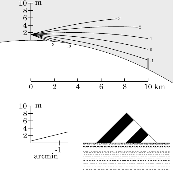
Because my simulation program normally shades temperature inversions, the whole lower atmosphere here appears gray in the ray diagram at the left. (The gray shading indicates an inverted lapse rate , not a duct.)
To compare with the Standard-Atmosphere case, click here. About twice as much of the target is visible in the looming model as in the Standard one: we see 4 of its stripes here, instead of 2. As Everett (1874) says, “The visible effect is precisely the same as if the convexity of the surface of the earth were diminished.” (Indeed, looming often makes the surface appear flat, or even concave.)
To see this much of the target in a Standard-Atmosphere simulation, a target distance of about 6 km would be needed, instead of the 10-km distance here. That illustrates why looming sometimes gives observers the impression that the object is abnormally nearby.
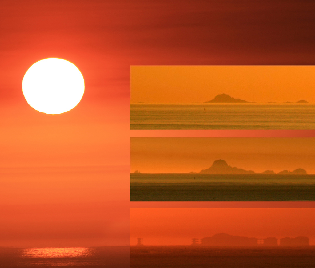
The classical example of looming is that described by William Latham (1798); but a very similar observation, also in the English Channel, was reported in even greater detail by John Parnell in 1869. A modern photograph showing looming (and some towering) of the Farallon Islands, as seen from San Francisco, is provided by Mila Zinkova.
Looming always decreases the dip of the apparent horizon, and increases its distance. The increased distance makes the sea horizon less distinct; in strong cases, its contrast becomes so low that the horizon is lost in haze, and is no longer visible to the naked eye. Then ships in the offing appear suspended in the air. This apparent “suspension” is an atmospheric-optics effect, but is not a mirage, as no inverted image is produced. The decreased dip adds to the appearance of “suspension”, especially to observers at elevated sites, where the dip is normally large. Marcella Pace has a short video that illustrates the effect; it sometimes accompanies looming, because of the increased distance and decreased dip of the apparent horizon. The horizon is most likely to be invisible when the ray curvature is nearly that of the Earth's surface.
 To produce sinking instead of looming, we need a model atmosphere with a
steeper lapse rate than normal. The
Standard Atmosphere
already has a lapse rate of 6.5°/km, but
convection limits lapse rates in the free atmosphere to about 10°/km.
However, much larger lapse rates are possible near the surface, where
looming is commonly observed.
To produce sinking instead of looming, we need a model atmosphere with a
steeper lapse rate than normal. The
Standard Atmosphere
already has a lapse rate of 6.5°/km, but
convection limits lapse rates in the free atmosphere to about 10°/km.
However, much larger lapse rates are possible near the surface, where
looming is commonly observed.
So I've used a model with that lapse rate (produced by setting the temperature at 1-km height to just 10° less than the surface temperature). The result is what you see at the left; you'll need to blink it against the reference case to notice the slight difference.
While blinking reveals the slightly lower position of the target's image here, a more obvious effect is the straighter rays in the ray diagram. Notice particularly the ray at −2′ altitude, which is almost tangent to the Earth's surface in the Standard-Atmosphere simulation, but obviously clears the surface here.
Note: The alignment setting was adjusted to make the apparent horizons coincide when you blink between the Standard and Sinking cases. This emphasizes the change in the amount of the target that's visible in the refracted image. But it conceals the fact that both the target image and the apparent horizon are shifted downward. The depression of the apparent horizon below the astronomical one is its dip , which is discussed on another page. Showing its small change in dip here would have been distracting.
Another, subtler, effect is visible when you blink these images. The simulated “sea surface” consists of equally-spaced rulings on the Earth; and the same pattern of rulings is used in both simulations. You can see that the rulings are more crowded together toward the apparent horizon here than in the reference case, so that the Earth appears more convex here than there. This is typical of sinking, and is often quite marked when the inferior mirage is seen: the Earth appears markedly convex. Vivid examples of this effect are shown in photographs at https://atoptics.co.uk/blog/yacht-on-waterfall-sea-mirage-opod/ and https://atoptics.co.uk/blog/opod-waterfall-sea/.
You can explore the consequences of various (constant) lapse rates by
using my JavaScript
calculator
to find the apparent altitude of a distant object.
For the values used here (height of eye, 1.5 m; height of target, 3 m;
target distance, 10 km; and lapse rate, 10 K/km) it gives an apparent dip
of 1.73 minutes of arc, which agrees well with the ray diagram.
However, my calculator cannot deal with ducts, so it cannot handle cases
with strong looming.
 A simple way to stretch the image is to have more looming at the top than
at the bottom, or more stooping at the bottom than at the top — or,
to combine these ideas, stooping at the bottom and looming
at the top.
A simple way to stretch the image is to have more looming at the top than
at the bottom, or more stooping at the bottom than at the top — or,
to combine these ideas, stooping at the bottom and looming
at the top.
So let's try a temperature profile that starts out with the maximum free-air lapse rate (10°/km) at the bottom, gradually changing to a strongly inverted lapse rate (−50°/km) a little higher up.
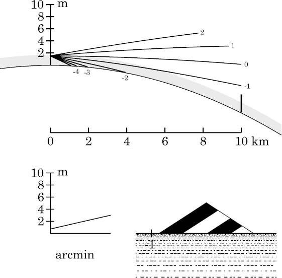
My first try at this used the temperature profile shown at the right below. I started with a piecewise-linear profile that switched from the 10°/km lapse rate at the surface to the strong inversion at 1 meter, and then smoothed it with the Gaussian-smoothing I've used in making other realistic profiles. The result is the simulation at the left.
Clearly, this works; but too well! We have not just an extremely elongated tip on the triangular target; it's actually acquired an inverted section, just below the top. We have a mirage here — which was not what I wanted. What went wrong?
The extremely stretched image of the target's tip, which the observer sees
near −1′ altitude, is produced by rays that are horizontal
just at the transition between the inversion and the underlying convective
layer (i.e., the boundary between the shaded inversion and the clear band
below it, in the ray diagram).
This transition region acts like a positive lens with a focal length a
little shorter than 2.5 km, so that an inverted, real image (in one
dimension) is formed; this image is the miraged zone.
(In fact, a little thought shows that the mirage here is an
ordinary mock mirage,
because the eye, at 1.5 m height, is above the bottom of the
inversion, at 1 m.)
Let's take a closer look at the atmospheric model used in this simulation.
To the right, you see the lowest 2 meters of the temperature profile. Obviously, the transition between the convective lapse rate at the surface and the strong inversion above it is too abrupt: it's concentrated into a height interval of about 30 cm. That has made the curvature of the profile near 1 meter so strong that it acts like a lens with a focal length shorter than 1/4 of the distance from eye to target — even though the temperature differences involved are only milli degrees. (Each small tick on the horizontal axis is just 0.002 degree.)
But my Gaussian-smoothing program can't make a more gradual transition region, because the lower tail of the Gaussian would run into the surface of the Earth. And if I move the transition region higher, it moves off the top of the target — in fact, it's already higher than I'd like in the simulation above.
What's needed is a different kind of smoothing. In fact, because the constant lapse rates (i.e., first derivatives of the temperature profile) in the looming and sinking simulations produced only image displacements, it seems that a model with a constant second derivative would be just what's required.
That meant writing another program to produce a parabolic splice between two linear segments, while keeping the first derivatives continuous at the joins. This is a straightforward exercise in analytic geometry; the result is the temperature profile shown at the right below.
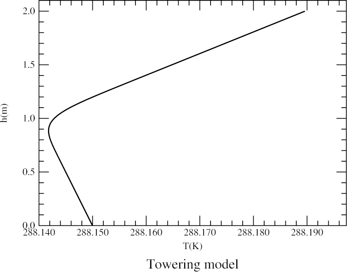
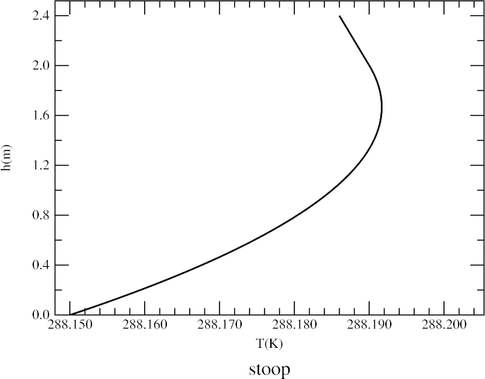
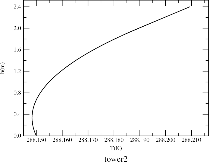 The figure on the right shows the lowest 2.4 meters of the new towering model.
As you can see, the desired continuity of slopes has been achieved
(at the 2-meter-high join between the parabolic lower part and the linear
profile above it). The inversion extends down to about 1/3 of a meter
above the ground.
The figure on the right shows the lowest 2.4 meters of the new towering model.
As you can see, the desired continuity of slopes has been achieved
(at the 2-meter-high join between the parabolic lower part and the linear
profile above it). The inversion extends down to about 1/3 of a meter
above the ground.
Although this kind of temperature profile is analytically simpler than the one above that produced a mock mirage instead of simple towering, it's physically unrealistic. So we have to regard it as a kind of toy model, useful for understanding the phenomenon of towering, but not something you'd find in the real world.
The essential feature here is a constant second derivative in the lowest 2 meters of the model. So the whole atmosphere below eye level (1.5 m), and even a little above it, should act like a uniform, weak positive lens: a magnifier. (Indeed, J. D. Everett showed in 1873 that such a profile acts like a lens.)
Of course, the real test of the model comes in the ray-trace and image
simulation, shown below.
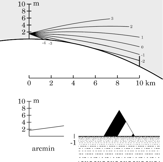 At last we have a simulation that shows almost uniform vertical stretching,
without complications. The sides of the stretched image are almost
perfectly straight. (If you
compare
this image with the ones for the
looming,
sinking,
or
Standard-Atmosphere
simulations, you'll see plainly the stretching of the target image here;
the top of the
undistorted target
is a right angle, while the top of the
towering image here is quite acute.)
At last we have a simulation that shows almost uniform vertical stretching,
without complications. The sides of the stretched image are almost
perfectly straight. (If you
compare
this image with the ones for the
looming,
sinking,
or
Standard-Atmosphere
simulations, you'll see plainly the stretching of the target image here;
the top of the
undistorted target
is a right angle, while the top of the
towering image here is quite acute.)
The smaller curvature of the temperature profile here (compared to that of the previous model) has made the lowest 2 meters of air into a weaker positive lens: a simple (though one-dimensional) magnifier. This atmospheric lens is so weak that the separation of conjugates here is considerably greater than the 10-km separation of eye and target; so no mirage is produced.
The straightness of the image sides here might seem a little surprising, because the top of the target is 3 m above the surface — a whole meter above the top of the magnifying layer of air. But the rays that reach the target's top have been below the 2-meter level through most of the interval between eye and target. More importantly, they only get above the 2-m level when they're very close to the target — a region in which ray curvature has little effect on what the observer sees.
However, if we had chosen a taller target, so that most of the optical path between its top and the observer was in the region of constant lapse rate above 2 meters, we would have seen a progressive diminution of the towering effect toward the target's summit. That means that a change in lapse rate above eye level can also affect towering (and stooping) of oblique rays. And, indeed, there are examples of this subtler kind of change in magnification among the various superior-mirage simulations — for example, here and here. (These links are to simulations for the piecewise-linear or “zigzag” temperature profile, where this effect is discussed; but the same features appear in more realistic simulations for an inversion with smoothed edges, here and here.)
Yet another mechanism for producing towering is shown in simulations that involve long paths inside a duct. The “reflections” at the top of the duct-producing inversion can act somewhat like a concave (magnifying) mirror. You can see an example of this effect here for the zigzag profile, and here for the corresponding smoothed inversion. (Of course, the “quasi reflection” at the top of the duct produces an inverted image; so those simulations show towering of a miraged image.)
Of course, towering is commonly seen in mirages, because where
their inverted and erect parts
join,
there's always a zone of great vertical magnification — i.e.,
towering.
 Having discovered how to produce a good (if artificial) example of
towering,
we can expect the same artifice to produce a similarly good example of
stooping. We'll start with an inversion at ground level, surmounted by a
region with a convective lapse rate, and join them with a parabola.
Having discovered how to produce a good (if artificial) example of
towering,
we can expect the same artifice to produce a similarly good example of
stooping. We'll start with an inversion at ground level, surmounted by a
region with a convective lapse rate, and join them with a parabola.
Here's the model, at the right. At the ground, it has the strongly-refracting inverted lapse rate of −50°/km that we used before; above 2 m height, we have the convective lapse rate (10°/km); and the lowest 2 meters are interpolated parabolically, as was done to make the towering model.
In this model, the lowest 2 meters of the atmosphere act like a negative (i.e., minifying) lens.
Notice what a tiny temperature change is needed to produce a considerable
effect in the image: only about 0°.04. This would be hard to measure in
the field, even with thermocouples or platinum resistance thermometry.
 The simulation at the left shows the result. As expected, the image of the
triangular target
is nicely squashed down: its vertex now appears obtuse,
instead of a right angle.
The simulation at the left shows the result. As expected, the image of the
triangular target
is nicely squashed down: its vertex now appears obtuse,
instead of a right angle.
Because the stooped image occupies only a fraction of a minute of arc in altitude, and is contained entirely between the −1′ ray (which passes above the top of the target) and the −2′ ray (which strikes the ground before the target), no tick marks are seen on the horizontal axis of the transfer-curve plot. (There is a tick mark for −1′, but it falls so far to the right of the plotted curve that it appears near the left foot of the target's simulated image.)
Notice that the inverted layer (shaded) is adjacent to the Earth's surface here. It produces considerable looming at the apparent horizon, because of the strong ray curvature there.
And, as we saw at the end of the towering discussion, stooping can also be produced when the line of sight crosses a boundary between strongly and weakly refracting layers; see here (or, more realistically, here), and here (or here), in the superior-mirage simulations, for example.
Like towering, stooping is nearly always seen in mirages: if one zone of the image is stretched vertically, that leaves less room for the remainder; so some other part of the image must be compressed. Indeed, the more complex the mirage, and the more images are repeated, the less room there is to fit everything into the available space. So complex mirages usually have extremely compressed (stooped) zones.
The nominal distance to the sea horizon from a height of 40 meters is just about halfway to these islands and rocks, so only their parts above about 40 m height should be visible. An eye height of about 150 m would be required to put the sea horizon at the islands, assuming standard refraction. Even from 66 m, the lower peaks, such as Seal Rock (the isolated feature at the left of the photographs), which is 25 m high, should be almost completely hidden.
However, a picture taken from a ship near the islands shows that everything is visible in Mila's pictures, even the low flats a meter or two above the sea. So looming is present in all these pictures taken from San Francisco.
Start by reading Pekka's introduction to these pictures. Then look at this array, which has a nice example of stooping in the upper right corner. Another instructive set is this one, which also has examples of towering and stooping.
Both sets have many images with mirages as well; count the red and white rings on the tower to see where extra ones appear. Indeed, most of the pictures on the lighthouse page show superior mirages — which are more complex than the milder refraction phenomena discussed here.
However, the more restricted sense in which the word is used today seems to have appeared around the beginning of the 19th Century; the OED quotes the “Library of Useful Knowledge” as saying that
The elevation of coasts, ships, and mountains above their usual level, when seen in the distant horizon, has long been known and described under the name of Looming.
Subsequently, the terms sinking , towering , and stooping were introduced, for the particular phenomena treated above. I have not been able to determine when and where these specific uses of these terms originated; but the earliest uses I know of are on p. 456 of William J. Humphreys's paper in the Journal of the Franklin Institute — later taken over almost verbatim in his well-known textbook Physics of the Air, where they appear on pp. 469–470.
The apparent size of objects … is the same as it would be without refraction.Thus, Lambert would deny the possibility of even towering and stooping, not to speak of mirages. This is entirely due to his oversimplified assumption of circular rays.
Copyright © 2009 – 2012, 2020, 2025, 2026 Andrew T. Young
or the
main mirage page
or the
GF home page
or the website overview page